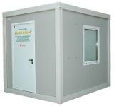
Hlorogen container on-site electrolytic system is the optimal solution when there is no adequate space to accommodate equipment for the disinfection of drinking water, as well as in the case when it is needed to place equipment for chlorination to a temporary location.
It consists of a storage container in which is the complete technological equipment installed, and as such is delivered to the buyer.
All the necessary equipment for remote monitoring and control is installed; therefore it can operate without a human crew. It is fast, reliable, efficient and cheap solution.
Characteristics of the system
Hlorogen Container Chlorination Station KDS3 – Characteristics of the systemKHS3 Container Station consists of : HLOROGEN H125 device, ADS – Automatic dosing system, PC for acquisition of sysstem data and remote control and managment by GSM or GPRS communication.
Hlorogen Container Chlorination Stations KHS3 capacity is 0,250 kg / h or 6,0 kg / day of equivalent chlorine.
Since no gaseous chlorine is present, water chlorination is absolutely safe due to system design. For production of sodium hypochlorite solution all that is needed is common salt, softened water and electric energy. Production expenses are up to two times lower compared to gaseous chlorine disinfection, or commercial sodium hypochlorite.
System is easy to use, demands only minimal maintenance and it is fully automated. Exploitation period is minimum 20 years.
E250 electrolyzers capacity to produce 250g/h, 6.0 kg/day is sufficient to disinfect the water with flow of 139 L / s in order to maintain the 0.5 mg/l residual prescribed by law.
The maximum water flow that can be disinfected with Hlorogen H125, depending on chlorine demand and desired residuals
|
Chlorine need (mg/l) |
Desired chlorine residual (mg/l) |
Chlorine consumption (g/min) |
NaOCl consumption (ml/min) |
Chlorine consumption (g/h) |
NaOCl consumption (l/h) |
Maximal water flow (l/s) |
|
0 |
0,3 |
4,16 |
416 |
249 |
24,9 |
231 |
|
0 |
0,4 |
4,15 |
415 |
249 |
24,9 |
173 |
|
0 |
0,5 |
4,17 |
417 |
250 |
25 |
139 |
|
0,1 |
0,5 |
4,14 |
414 |
248 |
24,8 |
115 |
|
0,2 |
0,5 |
4,16 |
416 |
249 |
24,9 |
99 |
|
0,3 |
0,5 |
4,13 |
413 |
248 |
24,8 |
86 |
|
0,4 |
0,5 |
4,16 |
416 |
249 |
24,9 |
77 |
|
0,5 |
0,5 |
4,14 |
414 |
248 |
24,8 |
69 |
|
0,6 |
0,5 |
4,16 |
416 |
249 |
24,9 |
63 |
|
0,7 |
0,5 |
4,10 |
410 |
246 |
24,6 |
57 |
|
0,8 |
0,5 |
4,13 |
413 |
248 |
24,8 |
53 |
|
0,9 |
0,5 |
4,12 |
412 |
247 |
24,7 |
49 |
|
1 |
0,5 |
4,14 |
414 |
248 |
24,8 |
46 |
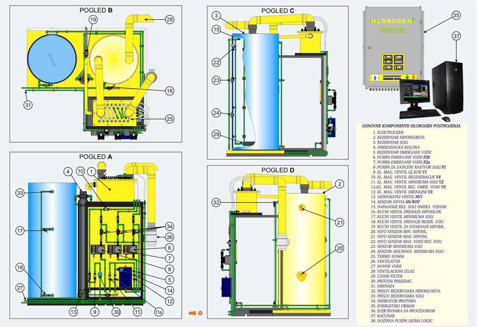
System Components
Hlorogen Container Chlorination Station KHS3 consists of the following componentsi:Operation Basics
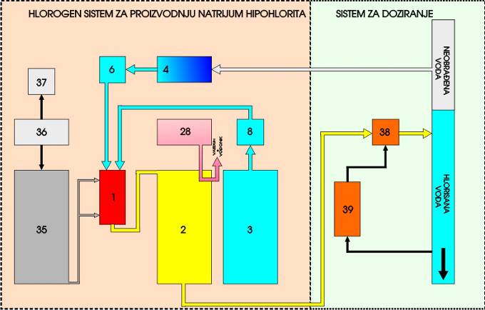
Hlorogen Container Chlorination Station KHS3 – Operation BasicsWater from the pipeline is filling water softener (4), calcium and magnesium ions are removed, and on the outlet of the softened water is obtained. Dosing pump (6) is transferring this water to the electrolyser where it is mixed with sodium chloride solution transferred from tank (3) by means of another dosing pump ( tank 3 contains saturated sodium chloride solution). Electrochemical reaction which results in conversion of sodium chloride into sodium hypochlorite is taking place in the electrolyser cell energized by direct electric current from energetic assembly (35) of the Hlorogen device Hypochlorite solution is stored in the tank (2). Hydrogen generated by conversion reaction is let in to atmosphere by means of ventilating system (28). Optimal hypochlorite production is achieved using system automatic arrangement (36). Sodium hypochlorite solution is injected by dosing membrane pumps (38) into pipeline with water to be disinfected. Residual chlorine analyzer (39) connected into regulation circuit with dosing pump keeps the concentration of residual chlorine in the water on the predetermined level. This is providing continuous production of disinfecting agent, automatic process control and automatic dosing and residual chlorine control.
Full system operation can be monitored through PC (37).
TECHNOLOGICAL SCHEME HLOROGEN PLANT


